We are committed to providing one-stop service for steel pipe products to customers around the world.
We are committed to providing one-stop service for steel pipe products to customers around the world.
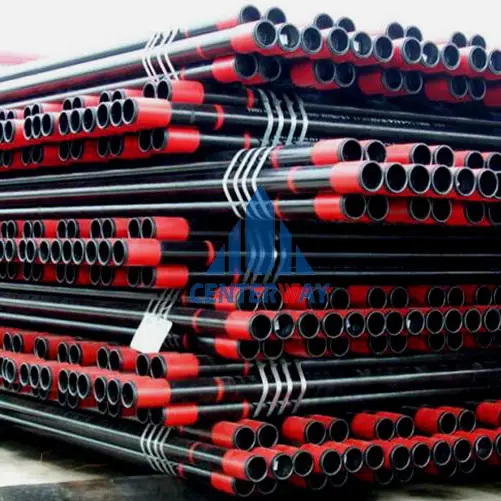
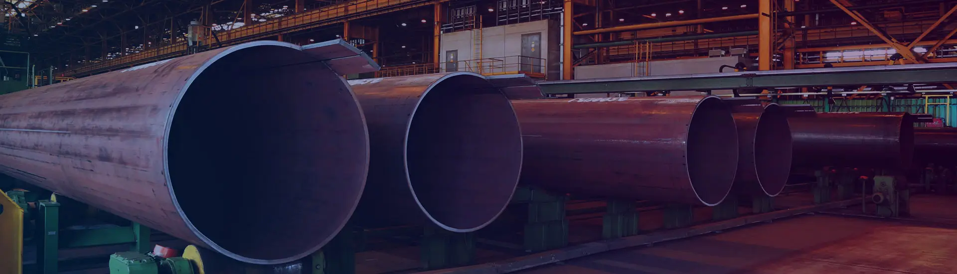
Casing is used for lining the complete borehole which has been dug into the ground to procure oil. Similar to the drill pipe, the oil well casing pipe is also subjected to axial tension, therefore they are required to be made from high-quality strong steel material. OCTG casing is large diameter pipe which are held in place in the borehole using cement.
The diameters of OCTG casing pipe range from 4.5″ to 36″. The well-cemented pipe acts as the structural component of the well and offer hole integrity. They prevent the well from collapsing when the drilling process is on. Good quality, well cemented casing can stay in place for the whole life of the well.
The oil well casing pipe are further divided into:
Conductor Casing – Conductor casing is the first boundary between the surface and the subsurface. It helps prevention of well collapse; it keeps away the groundwater and most importantly provides structural support. Conductor casing is installed in the ground by either drilling it or hammering it down. They are available in sizes ranging from 18″ to 36″.
Surface Casing – The purpose of Surface casing is primarily environmental and to ensure safety. It helps in separating the freshwater zones, offering protection from blowout and supporting the wellhead and blow out prevention equipment. Therefore surface casings are required to maintain very high safety standards. They are responsible for supporting the next casing in line. They may vary in size depending on their purpose, but the most common size of surface casing is 13 3/8”.
Intermediate Casing: Intermediate casing is not always required in all types of oil and gas production. If used, they are placed between the surface and the production casing. They are available in sizes ranging from 13 3/8” to 16”.
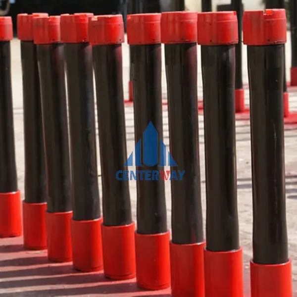
Production Casing – Production casing help provide structural integrity and pressure control of the hydrocarbon-bearing sections mainly during the production of oil.
Production Liner – Production liners can be suspended from the production casing or one of the previous casings. They help in reducing the cost significantly as the liner is not required to run through the full depth of the well. Liners can be pre-perforated to help save time and cost.
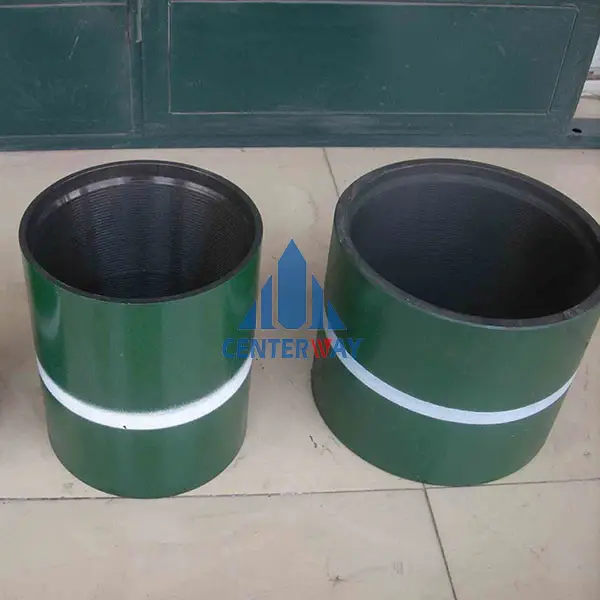
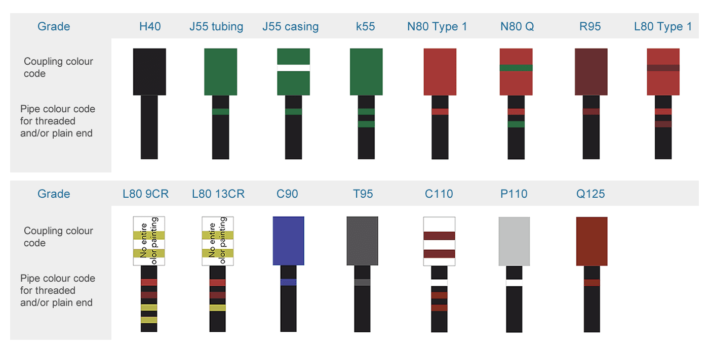
More casing pipes and their colors
API 5CT Well Casing Length:
|
API 5CT Casing |
Range 1 |
Range 2 |
Range 3 |
|
4.88~7.62 |
7.62~10.36 |
10.36~14.63 |
Dimension
|
Labels |
OD(mm) |
WT(mm) |
J55/K55 |
N80 |
L80 |
C90/T95 |
P110 |
Q125 |
|
|
4 1/2 |
9.5 |
114.3 |
5.21 |
PS |
- |
- |
- |
- |
- |
|
10.5 |
114.3 |
5.69 |
PSB |
- |
- |
- |
- |
- |
|
|
11.6 |
114.3 |
6.36 |
PSLB |
PLB |
PLB |
PLB |
PLB |
- |
|
|
13.5 |
114.3 |
7.37 |
- |
PLB |
PLB |
PLB |
PLB |
- |
|
|
15.1 |
114.3 |
8.56 |
- |
- |
- |
- |
PLB |
PLB |
|
|
5 |
11.5 |
127 |
5.59 |
PS |
- |
- |
- |
- |
- |
|
13 |
6.43 |
PSLB |
- |
- |
- |
- |
- |
||
|
15 |
7.52 |
PSLBE |
PLBE |
PLBE |
PLBE |
PLBE |
- |
||
|
18 |
9.19 |
- |
PLBE |
PLBE |
PLBE |
PLBE |
PLBE |
||
|
21.4 |
11.10 |
- |
PLB |
PLB |
PLB |
PLB |
PLB |
||
|
23.2 |
12.14 |
- |
PLB |
PLB |
PLB |
PLB |
PLB |
||
|
24.1 |
12.7 |
- |
PLB |
PLB |
PLB |
PLB |
PLB |
||
|
5 1/2 |
14 |
139.7 |
6.20 |
PS |
- |
- |
- |
- |
- |
|
15.5 |
6.98 |
PSLBE |
- |
- |
- |
- |
- |
||
|
17 |
7.72 |
PSLBE |
PLBE |
PLBE |
PLBE |
PLBE |
- |
||
|
20 |
9.17 |
- |
PLBE |
PLBE |
PLBE |
PLBE |
- |
||
|
23 |
10.54 |
- |
PLBE |
PLBE |
PLBE |
PLBE |
PLBE |
||
|
26.8 |
12.7 |
- |
- |
- |
P |
- |
- |
||
|
29.7 |
14.27 |
- |
- |
- |
P |
- |
- |
||
|
32.6 |
15.88 |
- |
- |
- |
P |
- |
- |
||
|
35.3 |
17.45 |
- |
- |
- |
P |
- |
- |
||
|
38 |
19.05 |
- |
- |
- |
P |
- |
- |
||
|
40.5 |
20.62 |
- |
- |
- |
P |
- |
- |
||
|
43.1 |
64.14 |
- |
- |
- |
P |
- |
- |
||
|
6 5/8 |
20 |
168.28 |
7.32 |
PSLB |
|
|
|
|
|
|
24 |
8.94 |
PSLBE |
PLBE |
PLBE |
PLBE |
PLBE |
- |
||
|
28 |
10.59 |
- |
PLBE |
PLBE |
PLBE |
PLBE |
- |
||
|
32 |
12.06 |
- |
PLBE |
PLBE |
PLBE |
PLBE |
PLBE |
||
|
7 |
20 |
177.8 |
6.91 |
PS |
|
|
|
|
|
|
23 |
8.05 |
PSLBE |
PLBE |
PLBE |
PLBE |
- |
- |
||
|
26 |
9.19 |
PSLBE |
PLBE |
PLBE |
PLBE |
PLBE |
- |
||
|
29 |
10.6 |
|
PLBE |
PLBE |
PLBE |
PLBE |
|
||
|
32 |
11.51 |
|
PLBE |
PLBE |
PLBE |
PLBE |
|
||
|
35 |
12.65 |
|
PLBE |
PLBE |
PLBE |
PLBE |
PLBE |
||
|
38 |
13.72 |
|
PLBE |
PLBE |
PLBE |
PLBE |
PLBE |
||
|
7 5/8 |
26.4 |
193.67 |
8.33 |
PSLBE |
PLBE |
PLBE |
PLBE |
- |
- |
|
29.7 |
9.52 |
- |
PLBE |
PLBE |
PLBE |
PLBE |
- |
||
|
33.7 |
10.92 |
- |
PLBE |
PLBE |
PLBE |
PLBE |
- |
||
|
39 |
12.7 |
- |
PLBE |
PLBE |
PLBE |
PLBE |
PLBE |
||
|
42.8 |
14.27 |
- |
PLB |
PLB |
PLB |
PLB |
PLB |
||
|
45.3 |
15.11 |
- |
PLB |
PLB |
PLB |
PLB |
PLB |
||
|
47.1 |
15.88 |
- |
PLB |
PLB |
PLB |
PLB |
PLB |
||
|
8 5/8 |
24 |
219.08 |
6.71 |
PS |
- |
- |
- |
- |
- |
|
28 |
7.72 |
- |
- |
- |
- |
- |
- |
||
|
32 |
8.94 |
PSLBE |
- |
- |
- |
- |
- |
||
|
36 |
10.16 |
PSLBE |
PLBE |
PLBE |
PLBE |
- |
- |
||
|
40 |
11.43 |
- |
PLBE |
PLBE |
PLBE |
PLBE |
- |
||
|
44 |
12.70 |
- |
PLBE |
PLBE |
PLBE |
PLBE |
- |
||
|
49 |
14.15 |
- |
PLBE |
PLBE |
PLBE |
PLBE |
PLBE |
||
|
9 5/8 |
36 |
244.48 |
8.94 |
PSLB |
- |
- |
- |
- |
- |
|
40 |
10.03 |
PSLBE |
PLBE |
PLBE |
PLBE |
- |
- |
||
|
43.5 |
11.05 |
- |
PLBE |
PLBE |
PLBE |
PLBE |
|
||
|
47 |
11.99 |
- |
PLBE |
PLBE |
PLBE |
PLBE |
PLBE |
||
|
53.5 |
13.84 |
- |
PLBE |
PLBE |
PLBE |
PLBE |
PLBE |
||
|
58.4 |
15.11 |
- |
PLB |
PLB |
PLB |
PLB |
PLB |
||
|
10 3/4 |
40.5 |
273.05 |
8.89 |
PSB |
- |
- |
- |
- |
- |
|
45.5 |
10.16 |
PSBE |
- |
- |
- |
- |
- |
||
|
51 |
11.43 |
PSBE |
PSBE |
PSBE |
PSBE |
PSBE |
- |
||
|
55 |
12.57 |
- |
PSBE |
PSBE |
PSBE |
PSBE |
- |
||
|
60.7 |
13.84 |
- |
- |
- |
PSBE |
PSBE |
PSBE |
||
|
65.7 |
15.11 |
- |
- |
- |
PSB |
PSB |
PSB |
||
|
113/4 |
47 |
298.45 |
9.53 |
PSB |
- |
- |
- |
- |
- |
|
54 |
11.05 |
PSB |
- |
- |
- |
- |
- |
||
|
60 |
12.42 |
PSB |
PSB |
PSB |
PSB |
PSB |
PSB |
||
|
13 3/8 |
48 |
339.72 |
8.38 |
- |
- |
- |
- |
- |
- |
|
54.5 |
9.65 |
PSB |
- |
- |
- |
- |
- |
||
|
61 |
10.92 |
PSB |
- |
- |
- |
- |
|
||
|
68 |
12.19 |
PSB |
PSB |
PSB |
PSB |
PSB |
- |
||
|
72 |
13.06 |
- |
PSB |
PSB |
PSB |
PSB |
PSB |
||
|
16 |
75 |
406 |
11.13 |
PSB |
- |
- |
- |
- |
- |
|
84 |
12.57 |
PSB |
- |
- |
- |
- |
- |
||
|
109 |
16.66 |
P |
P |
P |
- |
P |
P |
||
|
20 |
94 |
508 |
11.13 |
PSLB |
- |
- |
- |
- |
- |
|
30 |
96 |
762 |
16.13 |
PSLB |
- |
- |
- |
- |
- |
|
P-Plain end; S-Short round thread; L-Long round thread; B-Buttress thread; E-Extreme line; |
|||||||||
|
|
Tolerance |
|
|
D Outside Diameter |
Pipe Body |
D≤101.60mm,±0.79mm |
|
D≥114.30mm,+1.0%, -0.5%D |
||
|
Coupling |
±1%D |
|
|
t Wall Thickness |
0, -12.5%t |
|
|
Weight |
Single Lengths |
+6.5%,-3.5% |
|
Carload Lots or Order Quantity |
≥18144 kg(40000ib),0,-1.75% |
|
|
<18144 kg(40000ib),0,-3.5% |
||
|
|
type |
total elongation under load (%) |
yield strength (Mpa) |
tensile strength (Mpa) min |
hardness max |
||
|
min |
max |
HRC |
HBW |
|
|||
|
H40 |
- |
0.5 |
276 |
552 |
414 |
- |
- |
|
J55 |
- |
0.5 |
379 |
552 |
517 |
- |
- |
|
K55 |
- |
0.5 |
379 |
552 |
655 |
- |
- |
|
N80 |
1 |
0.5 |
552 |
758 |
689 |
- |
- |
|
N80 |
Q |
0.5 |
552 |
758 |
689 |
- |
- |
|
M65 |
- |
0.5 |
448 |
586 |
586 |
22 |
235 |
|
L80 |
1 |
0.5 |
552 |
655 |
655 |
23 |
241 |
|
L80 |
9 Cr |
0.5 |
552 |
655 |
655 |
23 |
241 |
|
L80 |
13 Cr |
0.5 |
552 |
655 |
655 |
23 |
241 |
|
C90 |
1 |
0.5 |
621 |
724 |
689 |
25.4 |
255 |
|
P110 |
- |
0.6 |
758 |
965 |
862 |
- |
- |
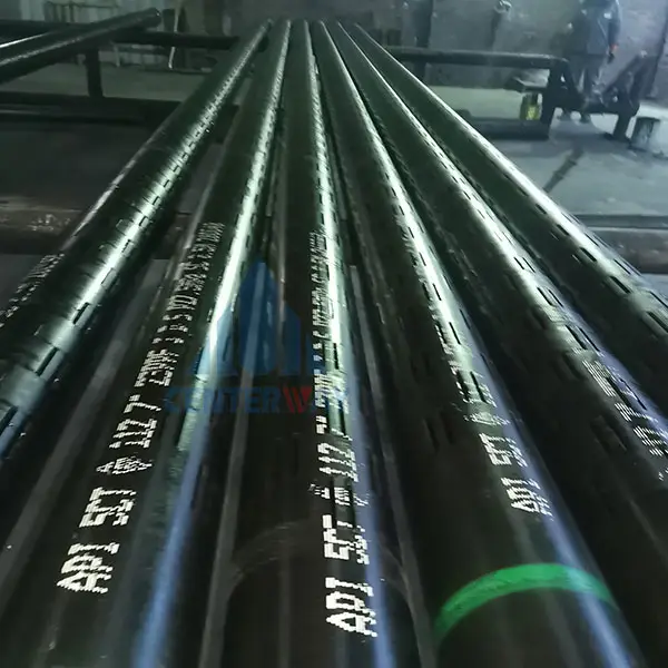
API Spec 5CT – Specification 5CT/ISO 11960, Specification for Casing and Tubing, Eighth Edition, Petroleum and natural gas industries-Steel pipes for use as casing or tubing for wells
Chemical Composition, Mass Fraction(%)
|
|
type |
C |
Mn |
Mo |
Cr |
Ni Max |
Cu Max |
P Max |
S Max |
Si Max |
||||
|
Min |
Max |
Min |
Max |
Min |
Max |
|
Max |
|
|
|
|
|||
|
H40 |
- |
- |
- |
- |
- |
- |
- |
- |
- |
- |
- |
0.030 |
0.030 |
- |
|
J55 |
- |
- |
- |
- |
- |
- |
- |
- |
- |
- |
- |
0.030 |
0.030 |
- |
|
K55 |
- |
- |
- |
- |
- |
- |
- |
- |
- |
- |
- |
0.030 |
0.030 |
- |
|
N80 |
1 |
- |
- |
- |
- |
- |
- |
- |
- |
- |
- |
0.030 |
0.030 |
- |
|
N80 |
Q |
- |
- |
- |
- |
- |
- |
- |
- |
- |
- |
0.030 |
0.030 |
- |
|
M65 |
- |
- |
- |
- |
- |
- |
- |
- |
- |
- |
- |
0.030 |
0.030 |
- |
|
L80 |
1 |
- |
0.43 |
- |
1.90 |
- |
- |
- |
- |
0.25 |
0.35 |
0.030 |
0.030 |
0.45 |
|
L80 |
9 Cr |
- |
0.15 |
0.30 |
0.60 |
0.90 |
1.10 |
8.00 |
10.0 |
0.50 |
0.25 |
0.020 |
0.010 |
1.00 |
|
L80 |
13 Cr |
0.15 |
0.22 |
0.25 |
1.00 |
- |
- |
12.0 |
14.0 |
0.50 |
0.25 |
0.020 |
0.010 |
1.00 |
|
C90 |
1 |
- |
0.35 |
- |
1.20 |
0.25 |
0.85 |
- |
1.50 |
0.99 |
- |
0.020 |
0.010 |
- |
|
P110 |
- |
- |
- |
- |
- |
- |
- |
- |
- |
- |
- |
0.030 |
0.030 |
- |
|
Q125 |
1 |
- |
0.35 |
- |
1.35 |
- |
0.85 |
- |
1.50 |
0.99 |
- |
0.020 |
0.010 |
- |
Mechanical properties of casing pipe
|
Grade |
Type |
Total elongation under load (%) |
Yield strength (min) |
Yield strength (max) |
Tensile strength min Mpa |
Hardness Max (HRC) |
Hardness Max(HBW) |
|
J55 |
- |
0.5 |
379 |
552 |
517 |
- |
- |
|
K55 |
- |
0.5 |
379 |
552 |
655 |
- |
- |
|
N80 |
1 |
0.5 |
552 |
758 |
689 |
- |
- |
|
N80 |
Q |
0.5 |
552 |
758 |
689 |
- |
- |
|
L80 |
1 |
0.5 |
552 |
655 |
655 |
23 |
241 |
|
L80 |
9Cr |
0.5 |
552 |
655 |
655 |
23 |
241 |
|
L80 |
13Cr |
0.5 |
552 |
655 |
655 |
23 |
241 |
|
C90 |
- |
0.5 |
621 |
724 |
689 |
25.4 |
255 |
|
C95 |
- |
0.5 |
655 |
758 |
724 |
- |
- |
|
T95 |
- |
0.5 |
655 |
758 |
724 |
25.4 |
255 |
|
P110 |
- |
0.6 |
758 |
965 |
862 |
- |
- |
|
Q125 |
All |
0.65 |
862 |
1034 |
931 |
- |
- |
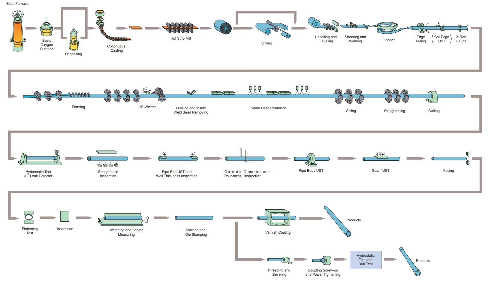
Manufacturing process of API casing
Steel ingot heating → hydraulic punching → reheating → extension → periodic rolling → reheating → sizing → cooling → straightening → pipe cutting → inspection
1. An annular heating furnace is required for ingot heating;
2. Punching and reheating with the hydraulic press;
3. The oil casing plant uses a two-roller guide plate extension machine for extension;
4. Re-use a disc heating furnace for periodic rolling, and use a non-entry furnace for reheating, cooling, straightening, pipe cutting, and inspection.


 English
 Español